
 ˹���á
˹���á �й��Թ�������
 �Թ���
�Թ��� ����ǡѺ���
 �Ըա�ê����Թ
 �Դ������
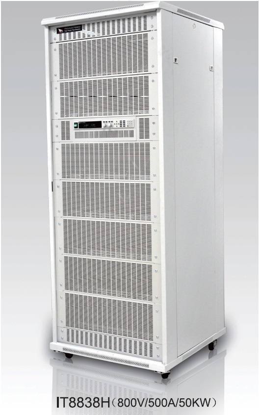
IT8800 series : DC ����硷�ԡ����Ŵ, ��������͡����袹Ҵ 200W �֧ 55KW
�������Թ���
-
�����Թ���
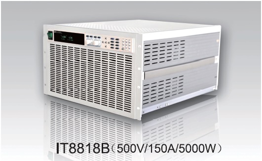
IT8812B/IT8814B/IT8817B/IT8817C/IT8818C
-
��Ҫ�
1,955 ����
������
ITECH
���
IT8812B/IT8814B/IT8817B/IT8817C/IT8818C
-
�������ش�����
29/04/2019 15:00
-
��������´�Թ���

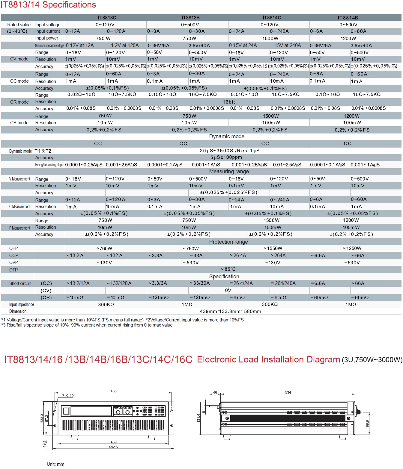
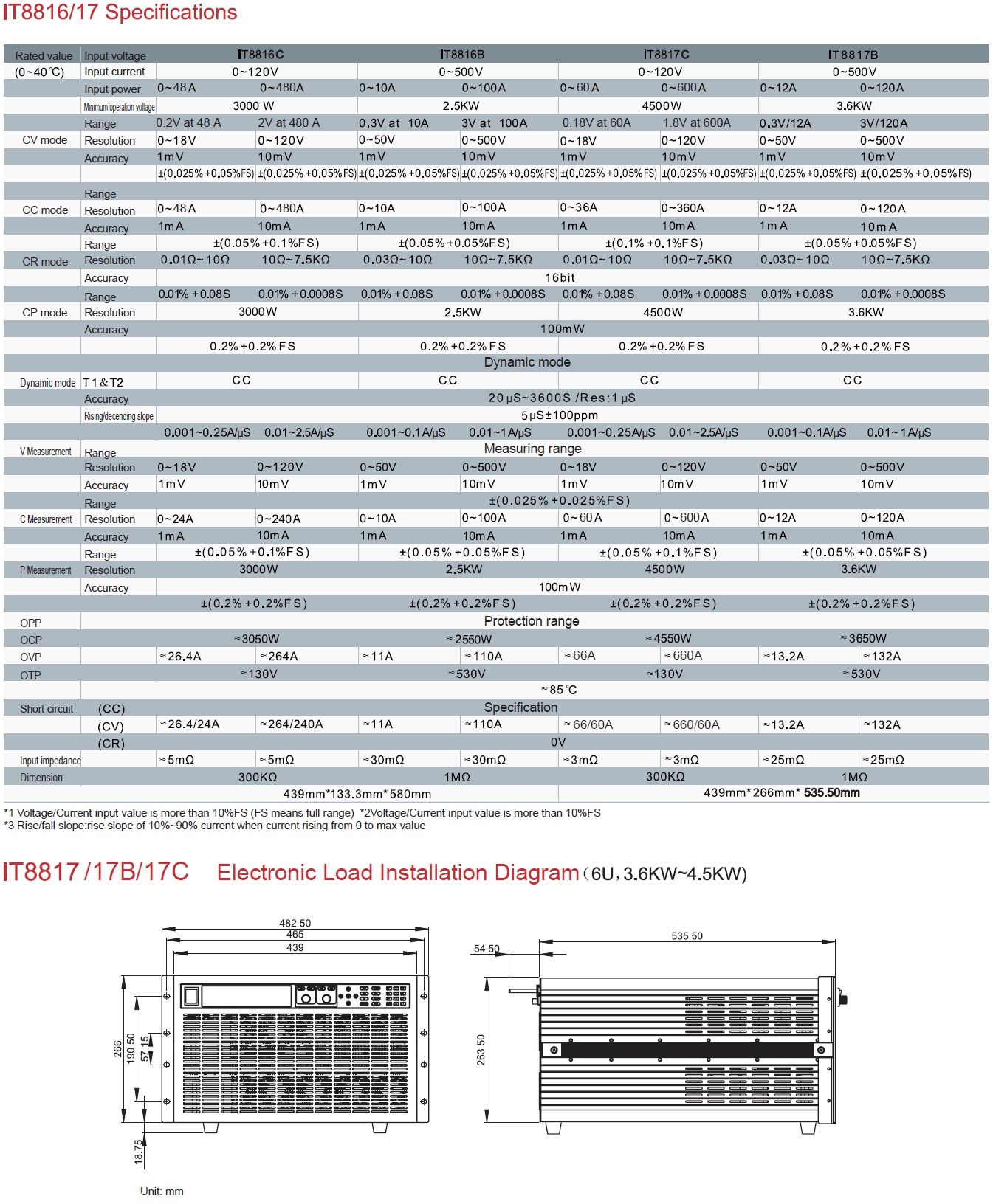
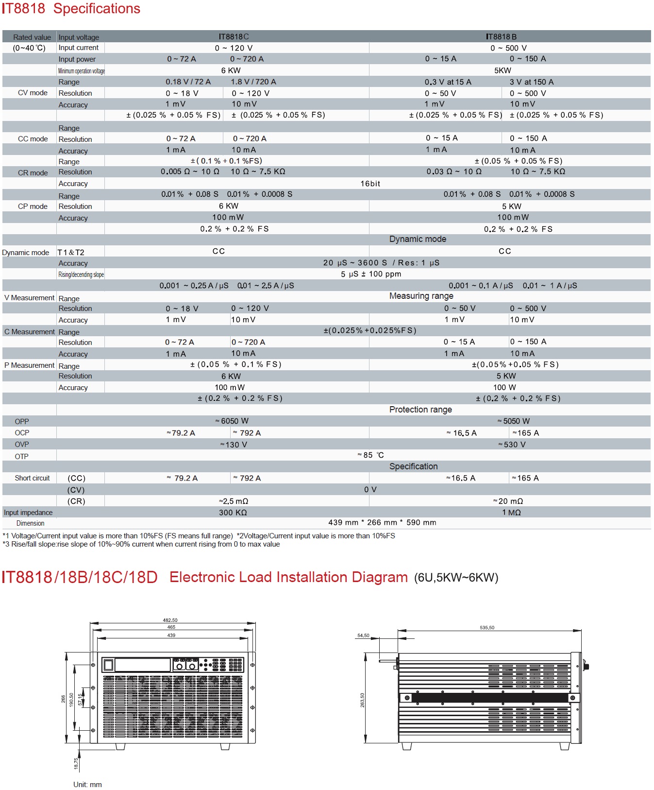
IT8800 series : DC ����硷�ԡ����Ŵ, ��������͡����袹Ҵ 200W �֧ 55KW
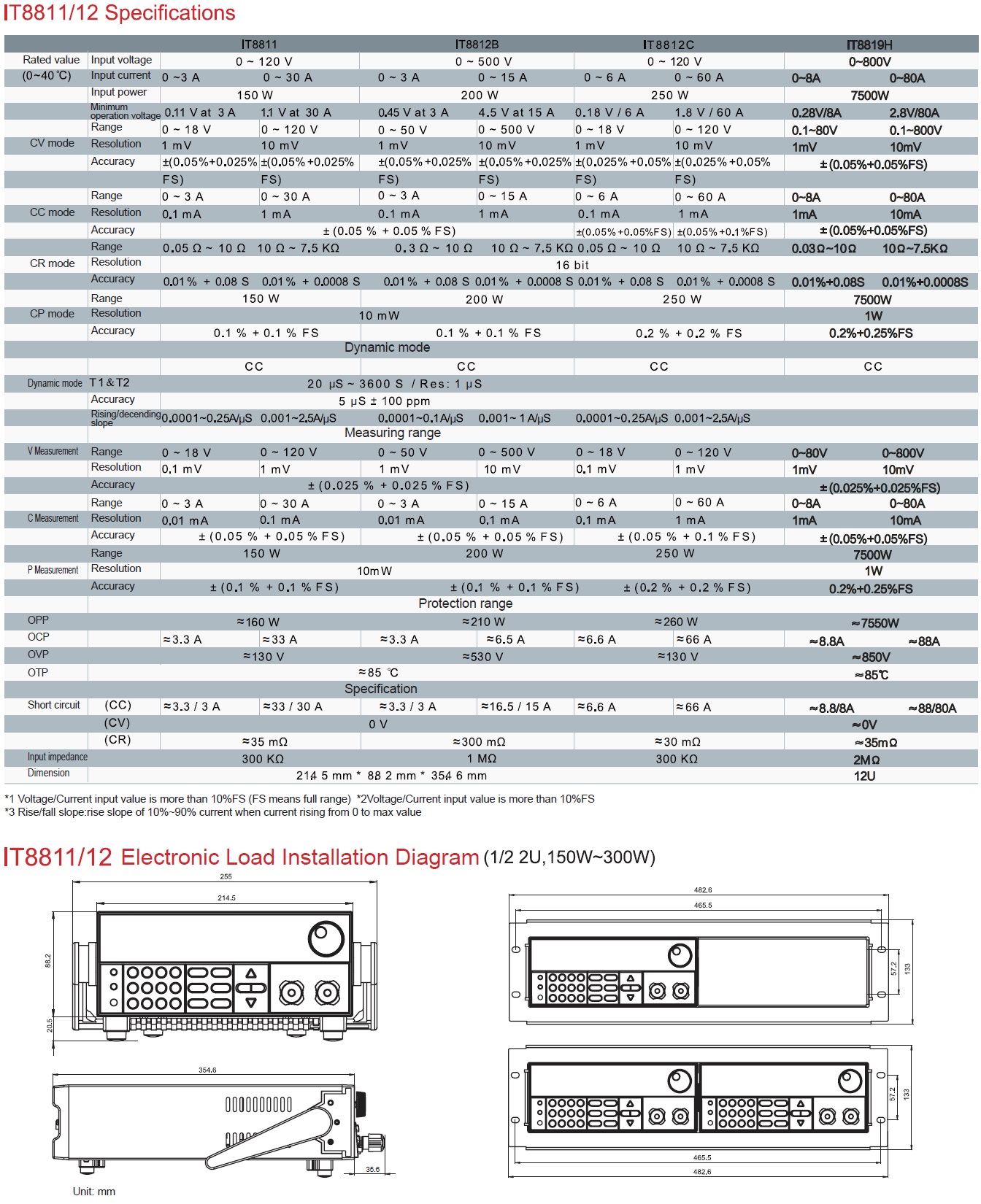
IT8800 series has wide power range 150W~10KW, voltage and cureent measurement speed up to 50KHZ, resolution up to 0.1mV/0.01mA, adjustable measurement current rising speed 0.001A/us~2.5A/us, built-in RS232/GBIP/USB interface. IT8800 series has wide application fields because of its high perfromance products, it has been applied to LED lighting, aerospace, automotive electronics and other fields. 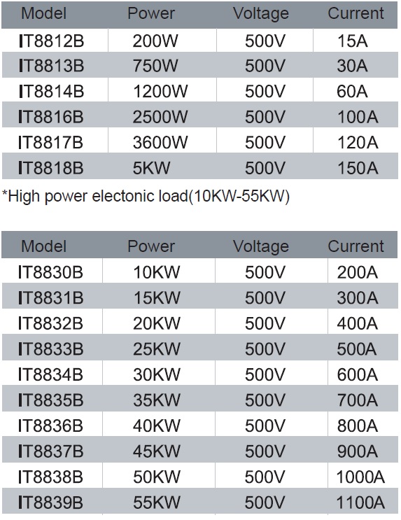
Highest power of single electronic load reach 600KW; customized-design is acceptable. 
Features ▪ VFD display ▪ Dynamic mode: up to 25 KHz ▪ Measurement resolution: 0.1mV , 0.01mA ▪ OVP/OCP/OPP/OTP and reverse polarity protection ▪ Measurement speed: up to 50KHz ▪ Four operation mode:CC/CV/CP/CR ▪ Remote sense ▪ Rotary knob, making the operation more easier ▪ Battery test function ▪ Memory capacity: 100 sets ▪ Adjustable current rising slope:0.001A/μS~2.5A/μS ▪ Short-circuit test function ▪ Dynamic test, auto-test ▪ With skid-resistant tripod and portable firm chassis ▪ Controlled by intelligent fans ▪ Built-in Buzzer as alarm signal ▪ Power off memory function ▪ CR-LED test ▪ OCP/OPP test ▪ Voltage rising speed test ▪ External analog control ▪ Support VISA/USBTMC/SCPI communication protocol ▪ Built-in RS232/USB/GPIB communication interface ▪ Controlled by computer via software 
Dynamic Mode: Up To 25KHz The transient test allows switching between two different load values. The function is used to test dynamic characteristic of power supply. 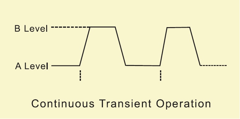
Adjustable Rising/Falling Speed Of Current List mode allows you to generate a complex current sequence. Moreover, the mode change can be synchronized with an internal or external signal, to accomplish dynamic and precise test. A list file includes following parameters: file name, step counts (range 2-84), time width of single step (0.00002s~3600s), step value and slope. The LIST function can make many kinds of complex sequences, to meet complicated test requirements. The slope range is 0.0001A/us~2.5A/us. 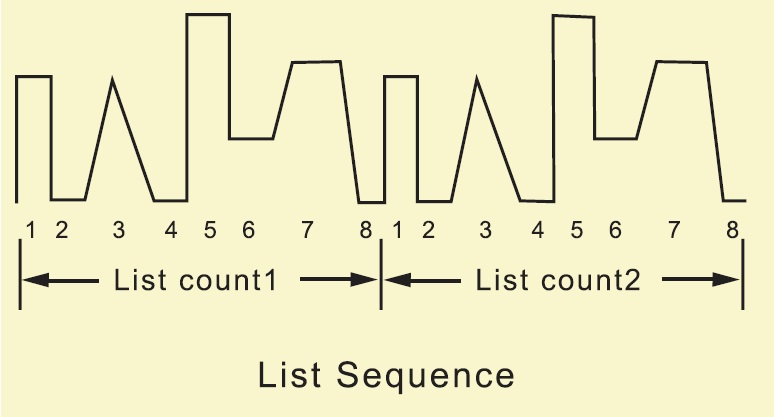
CR-LED Process Unique LED mode can provide LED power test, can be used in LED power simulation. As we all know the LED constant power output waveform usually have large current ripple. This is because of the ripple, traditional CR mode can’t simulate the actual characteristic of LED driver, its testing current and voltage will shake. Based on traditional CR mode, CR-LED mode adds the setting item of diode break-over voltage. Only when the input voltage is above the set value, will Voltage Rising/Falling Time Test IT8800 provides unique measurement function to test voltage rising/falling time. It can calculate the time from one voltage to anothervoltage. No need to use the oscilloscope. Voltage rising time is an important index of a device. Current Monitor IT8800 series products allows the users to monitor actual current through I-monitor terminal. Users could connect an oscilloscope to observe actual current. It will generate at 0-10V an al o g signal to represent to 0-100% rated current of the front panel. Communication Function Built-in standard RS232 /USB/GPIB communication interface, which can meet your different requirements. And the communication speed is faster than its the device with communication cable. 
Auto+A86:G111-test Function IT8800 auto-test function can simulate many kinds of testing. It totally can edit 10 test files, and can make connection between one file and ar.n othe Also you can chose the condition to stop the test: stop when testing pass or fail. Its adjustable current speed rate of rising and falling can make auto-test simulate various kinds of test waveform. OCP/OPP Test Process OPP test process: To start a OPP test, press “ shift+ trigger” to edit an OPP file. When the input voltage has reached VON point , power will begin to work after a delay time. The power value will increase by a step size at regular intervals. Simultaneously, the DC load will judge whether the input voltage is lower than OPP voltage (you need to set). If it is ,then the present current value will be compared to see if it is in the current range you’ve And then compare set, in this range, the power will continue to increase within the cut-off current range. OPP voltage with input voltage too. OCP test process:To start an OCP test, press “ shift +trigger”to enter OCP editing screen.After input voltage reaches Von point, the DC load start to draw a current from the source after a delay time. The current value will increase by a certain step size at regular intervals. Simultaneously, the DC load will judge whether the input voltage is lower than OCP voltage you’ve set. If it is, then the present current value will be compared to see if it is in the current range you’ve set. Within the range, the OCP test will Pass or Fail. IT8800 series programmable DC load, its maximum voltage is 800V, maximum current is 1500A, and its maximum power of single unit up to 55KW.More higher power of special specification can be customized design. 
Panel Operation It is very convenient to operate the IT8800 series electronic load panel, its shot-cut buttons are as follows: short circuit test, dynamic test, LIST test, data storage, data recalls, battery test, auto-test, test stop, test trigger, over current test, over power test. Parameters Setting It is quite convenient to set the parameters of IT8800 series , the users can use the panel button, to adjust pulsating knob, also can adjust the cursor around left and right keys, which to adjust stepper parameter values. This will eliminate the tedious steps of setting step. Working Mode The working mode of IT8800 series electronic load has CC, CV, CP , CR, It will make you easy to simulate various characteristics of load, which can save cost greatly. It support OVP,OCP,OPP,OTP,LRV, and it can set the protection point of current, voltage, and power. In every condition, it will make auditory alarm and cut off the circuit to ensure the safety during test. Remote Sense Function In CC, CV, CR and CP mode, when load consume high current, it will cause large voltage-drop on the connection wires between tested instrument and terminals of load. Using remote sensing, you can sense the voltage at the power supply’s terminals, effectively removing the effect of the voltage drop in the connection wires. remote input terminals, in order to avoid the voltage-drop because of too long wires, remote test allows testing on the input terminals to improve the test accuracy. Wire connection diagram of remote test is as follows: 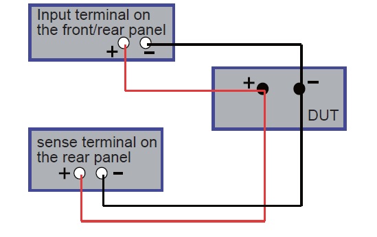
Support Living and Latch modes IT8800 series support with loading voltage setting, and it offers two kinds of load modes. Choosing Living means working goes after status, when choosing Latch, it means work load point latch with loadin g status. It can meet different test requirements. 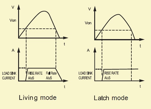
IT8800 series can keep common used paramaters in 100 sets non-volatile memory. It is convenient and quick to recall. The rear panel of IT8800 series has voltage failure indicate terminal, when load in the status of OVP or LRV, the indicate terminal of VF foot voltage failue will output high level. IT8800 series load allows the users to control current or voltage through the external analog terminals ( EXT PRG ). Input a 0-10V analog to adjust 0-100% rated voltage and current. IT8800 series products test the battery capability in CC mode. Make a program to set the stop conditions. There are three stop conditions can be chosen: stop voltage, stop capacity and stop timer. The discharge process of electronic load is terminated if the system checks the battery reaches the specified value or under an insecurity state. In testing procedure, the battery voltage, discharge current, discharge time and discharged capability will display on the front panel. 

 �Թ���
�Թ��� ��ǹ���Ŵᤵ����ͤ